A campervan electrical system is easier to understand when you stop seeing it as a cupboard full of equipment. It is one complete circuit: energy is collected, stored, distributed to an appliance, and returned to the battery.
Electricity in four ideas
Voltage (V)
Voltage is the electrical push. A system called “12V” does not sit at exactly 12.0V; battery voltage changes while it charges and discharges.
Current (A)
Current is the amount of electricity flowing now. It is measured in amps. More current means more heating in the cable, which is why high-current equipment needs thicker cable.
Power (W)
Power is how quickly a device is using energy. It is measured in watts. The basic relationship is watts = volts × amps.
Energy (Wh)
Energy is power used over time. A 40W fridge consuming power for five hours has used 200 watt-hours: 40W × 5h = 200Wh.
A 120W appliance on 12V draws about 10A because 120 ÷ 12 = 10. The same 120W on 24V draws about 5A. The appliance power is still 120W, but the higher-voltage system carries it with less current.
DC, AC and polarity
DC means direct current. Batteries, solar panels, USB sockets, many fridges and most campervan lighting use DC. It has a positive (+) and negative (−) side, and polarity must be correct.
AC means alternating current. UK household sockets supply AC. A van uses an inverter to turn battery DC into mains-style AC. That conversion wastes some energy, so a 500W AC appliance takes more than 500W from the battery side.
PV means photovoltaic—the solar-panel side of the system. MPPT means Maximum Power Point Tracking, the method used by a solar charge controller to obtain useful power from the panels and turn it into controlled battery charging.
A realistic small-system layout
This installation-style view shows the equipment as it might be arranged on a board. Every conductor lands on a stud, terminal or connector. The light and fridge have separate positive fuses and separate negative returns.
Separate circuits: the light leaves fuse F1; the fridge leaves fuse F2. Each appliance has its own negative return to the negative busbar. Cable and fuse ratings are deliberately omitted because they must be calculated for the actual equipment and cable lengths.
What each part does
Leisure battery
Stores energy for the living area. It is separate from the starter battery in a typical installation.
Busbar
A solid common connection point. A positive busbar distributes the supply; a negative busbar gathers the return cables.
Fuse
Protects the cable from overheating if too much current flows. The fuse rating must suit the cable and the expected load. A fuse is not an on/off switch.
Isolator
A switch intended to disconnect part of the system for maintenance or an emergency. It does not replace a fuse.
Shunt
A calibrated measuring point in the battery-negative cable. It must be the first component after battery negative so every amp entering or leaving the battery passes through it.
MPPT solar charger
Maximum Power Point Tracking. It finds the panel's useful operating point and converts that power into the correct charging voltage and current for the battery.
BMS
Battery Management System. In a lithium battery it monitors cells and can disconnect charging or loads if voltage, current or temperature moves outside its limits.
Inverter
Turns battery DC into mains-style AC. Large inverters draw very high current from a 12V battery and need short, heavy cables and suitable protection.
The shunt's non-negotiable rule
A shunt measures current in both directions: discharge current when equipment is running and charge current when solar, alternator or mains charging is active. The battery monitor uses those measurements over time to calculate SOC—state of charge.
Battery negative goes directly to the shunt terminal marked BATTERY MINUS. Nothing else connects to this battery post or this side of the shunt.
The negative busbar, loads, inverter and every charger connect on the SYSTEM MINUS side.
If a fridge, MPPT, inverter or any other device is connected directly to battery negative, its current bypasses the shunt. The monitor cannot count that energy and may show more charge remaining than the battery really has.
See Victron's official SmartShunt connection drawing and installation instructions →
The abbreviations you will meet
SOC
State of charge: the battery monitor's estimate of how full the battery is, shown as a percentage.
Ah
Amp-hours: battery charge capacity. It is useful only when the battery voltage is also known.
Wh
Watt-hours: stored or used energy. Wh makes it easier to compare loads and batteries operating at different voltages.
PV
Photovoltaic: the technical word for equipment that turns light into electricity. “PV array” simply means the group of solar panels.
Voc
Open-circuit voltage: panel voltage when nothing is drawing power. It rises in cold conditions and is used to check the controller's absolute voltage limit.
Vmp
Voltage at maximum power: the panel voltage near its most productive working point under the stated test conditions.
Isc
Short-circuit current: a panel test value used when checking controller, cable and protection limits. It is not the normal charging current.
Imp
Current at maximum power: the panel current at its rated maximum-power point.
STC
Standard Test Conditions: a laboratory reference used for panel ratings—1,000W/m² of light, a 25°C cell temperature and a standard solar spectrum. It allows fair comparison; it is not a promise of everyday output.
DoD
Depth of discharge: the percentage of battery capacity that has been used. An 80% DoD means 20% remains.
Connectors and cable ends
A sound circuit depends as much on its joints as its cable. Loose or badly crimped connections add resistance, create heat and cause voltage drop.
-
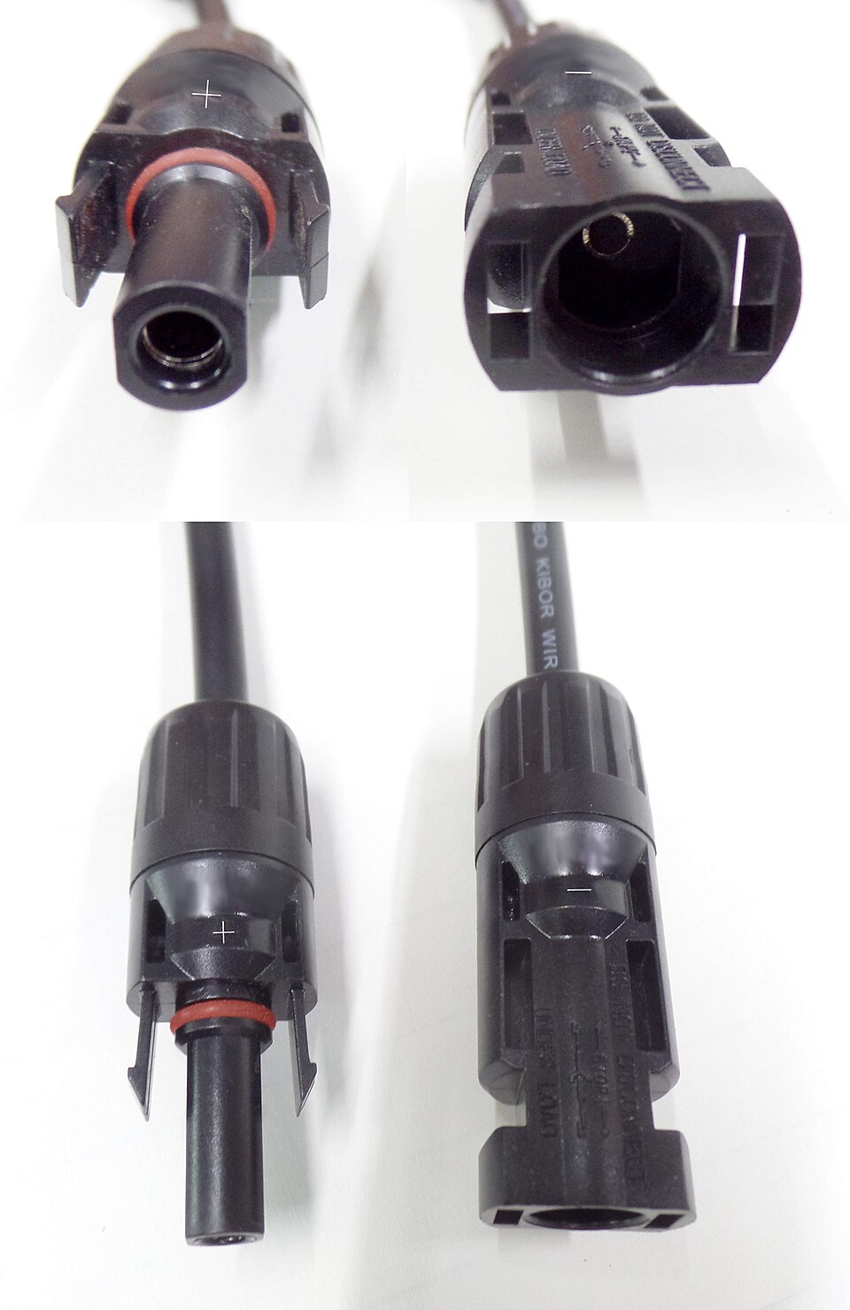
MC4: the common locking, weather-resistant connector fitted to solar-panel leads. Panels usually arrive with one positive and one negative MC4-style lead. Use the correct crimp tool and matching contacts; the moulded connector shape alone is not a substitute for checking the + and − markings.
 View larger
-
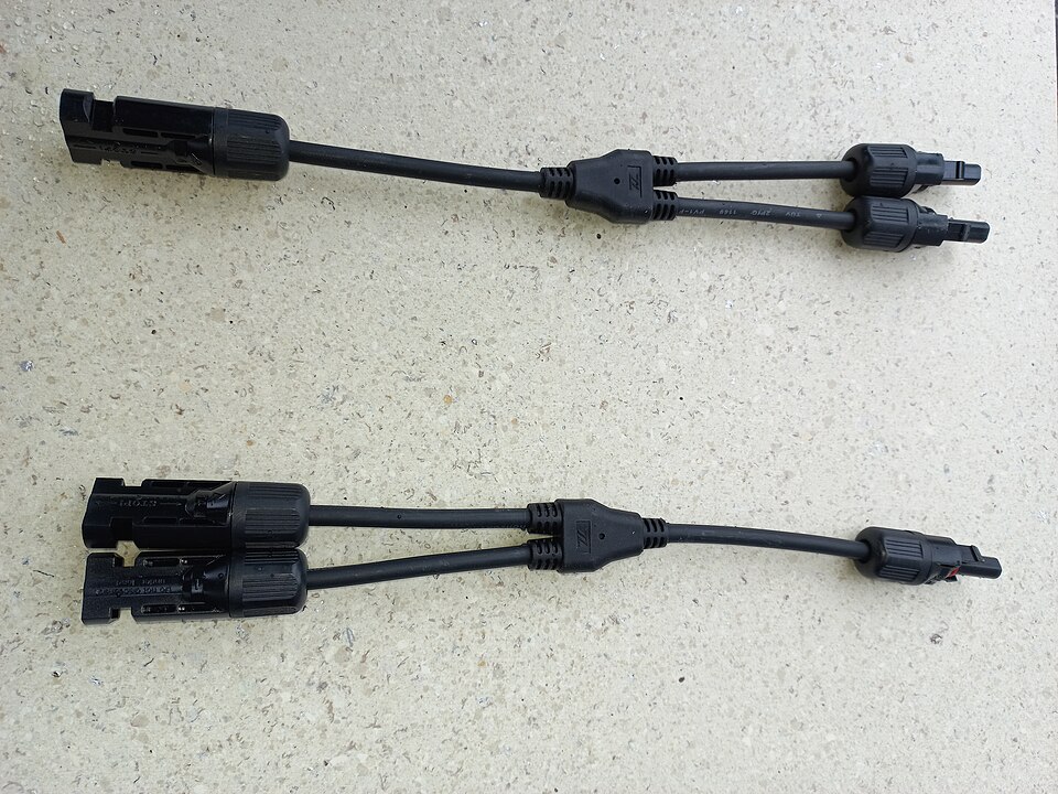
MC4 Y-branch: a matched pair of splitters used to join panel strings in parallel. Parallel wiring increases current, so the cable, connector and controller limits must be checked.
 View larger
-
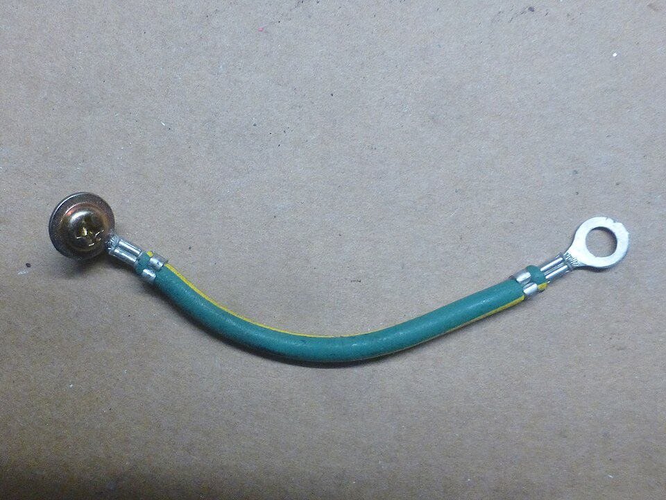
Ring lug: a metal eye crimped onto cable and bolted to batteries, busbars, fuses and shunts. Use the correct lug for both the cable size and stud size.
 View larger
-
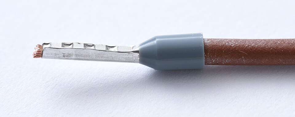
Ferrule: a sleeve crimped over fine-stranded cable before it enters a compatible screw or clamp terminal. Use one only where the equipment maker permits it.
 View larger
-
Heat-shrink: protects and supports a finished crimp, but it cannot rescue a poor mechanical joint.
 View larger
Photo credits and licences
- MC4 by Orion Lawlor, CC0 1.0
- MC4 Y-branch by Asurnipal, CC BY-SA 4.0
- Ring lug by Talonola, CC BY-SA 4.0
- Ferrule by Simon A. Eugster, CC BY-SA 3.0
- Heat-shrink by oomlout, CC BY-SA 2.0
Photographs are reduced-size copies from Wikimedia Commons.
Plan the system in this order
- List every load. Record watts or amps, quantity, hours per day, and whether it runs on 12V DC or through an inverter.
- Calculate daily energy. Multiply watts by hours for each item, then add the watt-hours together.
- Choose reserve time. Decide how long the system should last without useful solar or driving.
- Choose the battery. Check usable capacity, continuous current, surge current, charging limits, temperature limits and the battery-management-system rating.
- Choose charging sources. Solar, alternator and mains chargers must all support the battery chemistry and voltage.
- Draw the circuit. Put every fuse, isolator, busbar, shunt, connector and cable termination on the drawing.
- Size cables and protection. Use current, cable length, acceptable voltage drop, installation method and temperature—not guesswork.
- Check access. Fuses and isolators must remain reachable after the furniture is built.
A simple energy example
At a nominal 12V, 615Wh is roughly 51Ah before allowing for conversion losses, reserve and the battery's usable-capacity limit. This is why daily watt-hours are the useful starting point.
Before switching on
- Check every cable against the drawing and label both ends.
- With the system unpowered, check continuity and confirm that positive is not shorted to negative.
- Check every crimp with a firm pull and tighten terminals to the manufacturer's stated torque.
- Fit fuses only after the cable and polarity checks are complete.
- Follow each equipment manual's power-up order. Many solar controllers should see the battery before the panels.
- Test one circuit at a time, watching voltage, current and unexpected heat.
Sources worth keeping
Primary references: Victron Energy — Wiring Unlimited, Victron's DC wiring and connector guide, Victron's official SmartShunt installation instructions, and NREL's photovoltaic terminology reference. Equipment manuals and applicable electrical standards take priority.